Buyers often send two lines: fibre count and span. That may be enough for a budget number, but not for production. Two routes with the same pole spacing can need different cable constructions because wind exposure, temperature, line deviation, sag allowance and attachment hardware change the load on the cable. African projects must be assessed by country, region and route; the continent is not one climate zone.
Start with actual pole spacing
Use the longest measured span, not the average. Mark road crossings, river crossings, sharp direction changes and exposed high points separately. A 70-metre average route can still contain one 140-metre crossing that controls the cable design.
For a new route, send a pole schedule or a simple table showing pole number, distance to the next pole and any change in direction. For an existing line, photos of the poles and attachment points are often more useful than a long written description.
Separate routine spans from special crossings
Do not automatically increase the whole order to match one exceptional crossing. In some projects, the normal route can use one ADSS construction while a road or valley crossing is checked separately. This can reduce unnecessary cable weight and cost, but it must be agreed before drum lengths are fixed.
Use the project's wind and temperature basis
Open plains, coastlines, escarpments and valley crossings can have different wind exposure. High daytime temperature affects sag and installation planning, while a cooler installation morning can produce a different tension condition. The network designer should provide wind, temperature and any ice or exceptional-load assumptions. A supplier should state the loading basis behind quoted tensile and sag values instead of treating “hot climate” as a material specification.
Check UV, pollution and electrical exposure separately
Black outdoor polyethylene is common, but the project should define UV and environmental performance. Coastal salt, dust, industrial pollution and bushfire exposure are separate route risks. If the cable shares power-line structures, provide line voltage and attachment position so electrical-field and tracking considerations can be assessed. The phrase “on power poles” is not enough to choose PE or an anti-tracking sheath.
Fibre count, longest span, typical span, route length, wind condition, pole type, required sag, jacket preference, installation hardware and delivery country.
PE or AT outer jacket?
The jacket decision depends on the electrical environment and the operator's specification. PE is common for many telecom pole routes. AT jacket may be requested where the cable is installed in a higher electrical-field environment near power conductors. The position on the pole and the line voltage matter; “installed on power poles” by itself is not a complete answer.
Match cable and hardware together
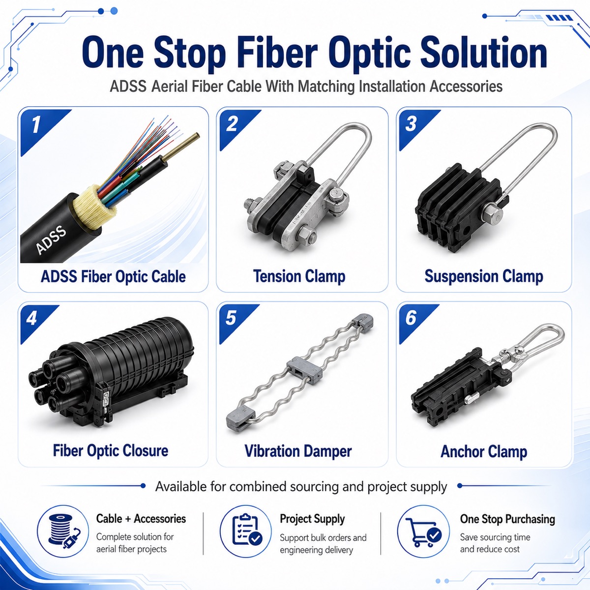
Suspension and tension assemblies must suit the cable diameter, span and route angle. Ask the supplier to confirm the finished cable diameter before clamps are ordered. Mixing cable from one drawing with hardware selected from another diameter range is a common, avoidable site problem.
Plan drum length from installation sections
Total kilometres do not determine drum length. Pulling method, storage area, pole access, splice locations and transport limits do. A practical drum schedule reduces unnecessary joints and prevents a drum from being too heavy for the equipment available on site.
Compare quotations using the same tension definitions
Rated tensile strength, maximum allowable tension, everyday tension and installation tension are not interchangeable. Ask each supplier to identify the value stated, the associated load case and the cable diameter and weight. Compare sheath, fibre performance, hardware scope, drum plan and evidence together. A lower number or lower price may simply reflect a different assumption rather than a more efficient design.
What we confirm before production
- Fibre type and count.
- Required span and mechanical design conditions.
- Outer jacket and cable marking.
- Finished diameter and compatible fittings.
- Drum length, labels and export packing.
- Optical test records required before loading.
The final mechanical design should be checked against the project specification and the applicable aerial optical cable standard. IEC 60794-3 covers outdoor optical cables, while project owners may add their own load, weather and installation requirements.